Pest Management Guidelines – Turfgrass
Turfgrass IPM Guidelines
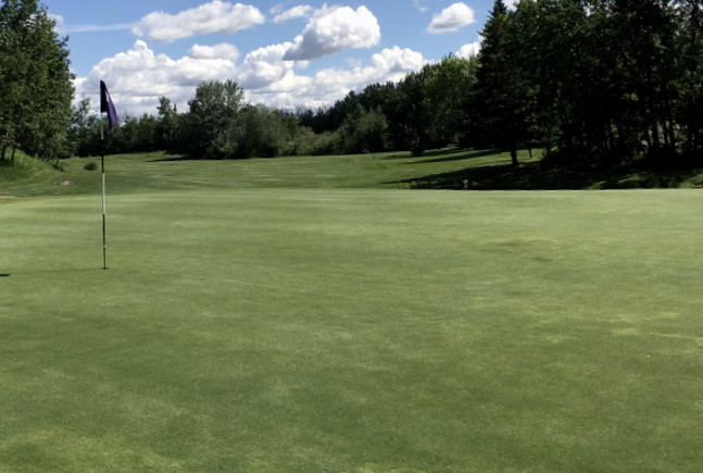
IPM guidelines for turfgrass. 2024 pest management guidelines for commercial turfgrass. Managing and controlling pests, weeds and diseases in turfgrass, lawns, and grasses.
Read Updated Turfgrass Guidelines
Turfgrass Pest Management Guidelines Summary:
1. Pesticide Information
2. Sprayer Application Technology
3. Turfgrass Culture
4. Plant Growth Regulators
5. Disease Management
6. Insect Management
7. Weed Management
8. Wildlife Management for Turfgrass
9. Index of Common and Trade Names of Pesticides Registered for Use on Turfgrass
10. Glossary
Trade names used herein are for convenience only. No endorsement of products is intended, nor is criticism of unnamed products implied.
These guidelines are not a substitute for pesticide labeling. Always read the product label before applying any pesticide.
The guidelines in this bulletin reflect the current (and past) authors’ best effort to interpret a complex body of scientific research, and to translate this into practical management options. Following the guidance provided in this bulletin does not assure compliance with any applicable law, rule, regulation or standard, or the achievement of particular discharge levels from agricultural land.